Pool-Spa Installation
SIMPLE Installation 
In our commitment to simplify the installation process of CHEMTROL® controllers, we have streamlined everything onto a customized assembly manifold, prepared for easy connection.
This approach ensures proper water sampling around the sensors, facilitating a hassle-free installation that minimizes the integration work required to get your water treatment system operational.
For architects and engineers preparing bids, listed below are various installation options to accommodate diverse requirements.
Bypass line assembly, programmable controller (PC) range
A choice of 6 models available
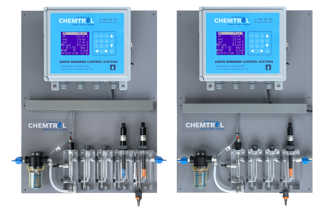
MODEL 1
Monobloc cell housing for water analysis
Designed to seamlessly integrate with the PC programmable range controllers
Free and Total chlorine (ppm) sensors with pH, ORP, TDS and Temperature.
By-pass line assembly features a monobloc cell housing fitting with Inlet & Outlet service valves connected to 3/8″ tubing, inline strainer, flow indicator, flow control valve, safety flow switch, and water sample valve. It is available for both single and dual chlorine sensors (ppm).
The Controller assembly and the By-pass line assembly share a grey PVC backboard, each measuring 600×400 mm.
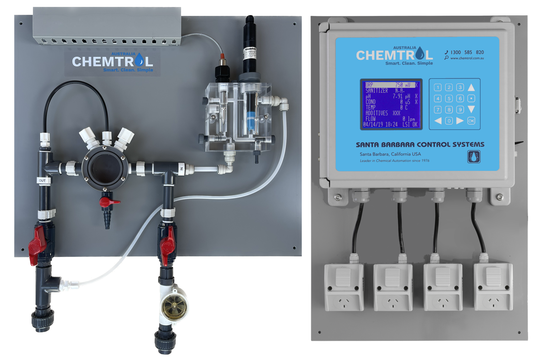
MODEL 2
Suitable for PC1555, PC110c & PC5000
Chlorine (ppm) sensor with pH, ORP, TDS and Temperature.
Seamless controller setup: Choose between hardwired dosing pumps or General Purpose Outlets (GPOs) for easy dosing equipment connection.
Our Flow Cell Assembly (FCA) features a clear acrylic flow cell for Chlorine sensor (ppm), 2 flow control valves, a water sample valve, safety flow switch, and probes holder fitting.
The Controller assembly comprises a grey PVC backboard (600×400 mm), while the By-pass line assembly measures (600×500 mm).
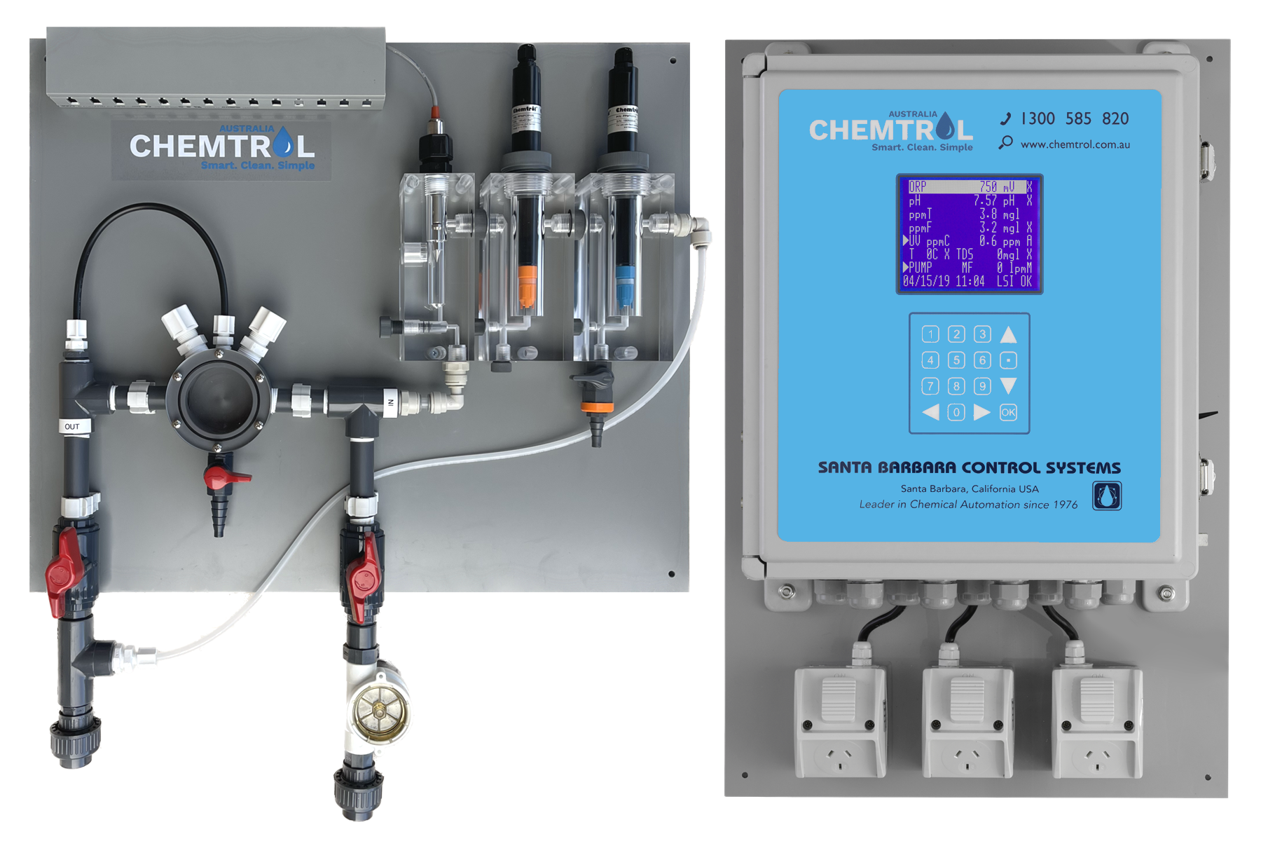
MODEL 3
Suitable for PC2100A & PC5100
Dual ppm control, Free & Total chlorine sensors with pH, ORP, TDS and Temperature.
Seamless controller setup: Choose between hardwired dosing pumps or General Purpose Outlets (GPOs) for easy dosing equipment connection.
Our Flow Cell Assembly (FCA) features 2 clear acrylic flow cells for Chlorine sensors (ppm), 2 flow control valves, a water sample valve, safety flow switch, and probes holder fitting.
The Controller assembly comprises a grey PVC backboard (600×400 mm), while the By-pass line assembly measures (600×500 mm).
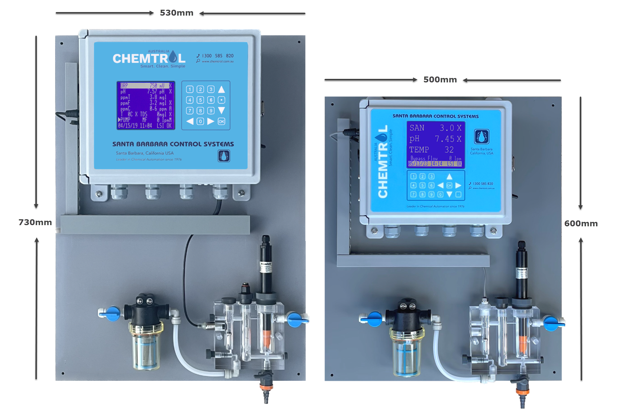
MODEL 4
Monobloc cell housing for water analysis
Suitable for PC1555 & PC110c series
pH with chlorine (ppm) sensor and temperature
By-pass line assembly includes a monobloc cell housing fitting for Chlorine sensor (ppm) control, pH control, and optional Temperature monitoring. It features Inlet & Outlet service valves connected to 3/8″ tubing, inline strainer, flow indicator, flow control valve, safety flow switch, and water sample valve.
Specifically tailored for compatibility, the PC1555 comes with a 600 x 500 mm PVC sheet backboard, while the PC110c is equipped with a larger 730 x 530 mm PVC sheet backboard.
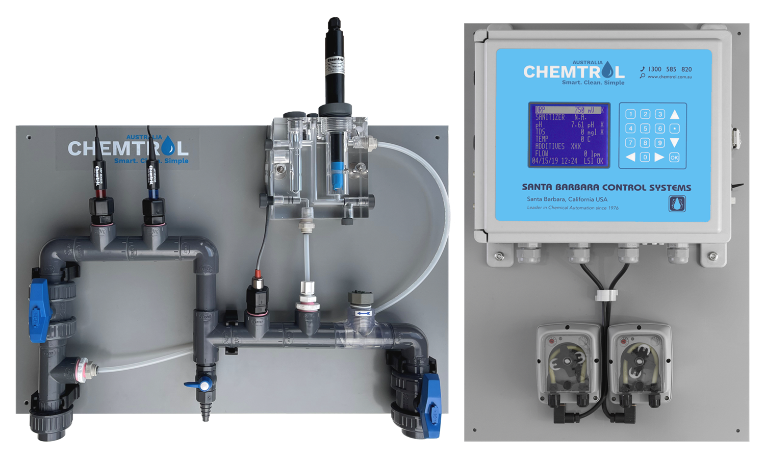
MODEL 5
Suitable for PC110c
Chlorine (ppm) sensor with pH, ORP, TDS, and temperature capabilities. Designed for pools, spas, water parks, and similar applications.
The controller wiring options include hardwired dosing pumps or General Purpose Outlets (GPOs) ready for connection to dosing equipment. The by-pass line assembly includes two flow control valves, a safety flow switch, a clear acrylic flow cell for the chlorine sensor, a flow indicator, and a water sample valve.
Both the Controller assembly and the By-pass line assembly are mounted on a grey PVC backboard measuring 600×400 mm.
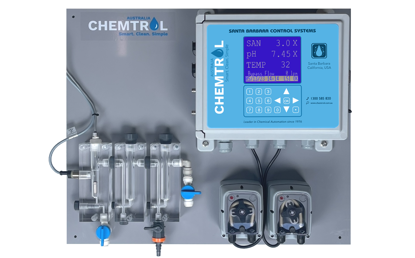
MODEL 6
Monobloc cell housing for water analysis
Suitable for PC1500
pH and ORP control with Temperature monitoring.
By-pass line assembly includes a monobloc cell housing fitting for pH and ORP control, with temperature monitoring. It features Inlet & Outlet service valves connected to 3/8″ tubing, safety flow switch, flow indicator and water sample valve.
Specifically tailored for compatibility, the PC1500 comes with a 600 x 500 mm PVC sheet backboard.
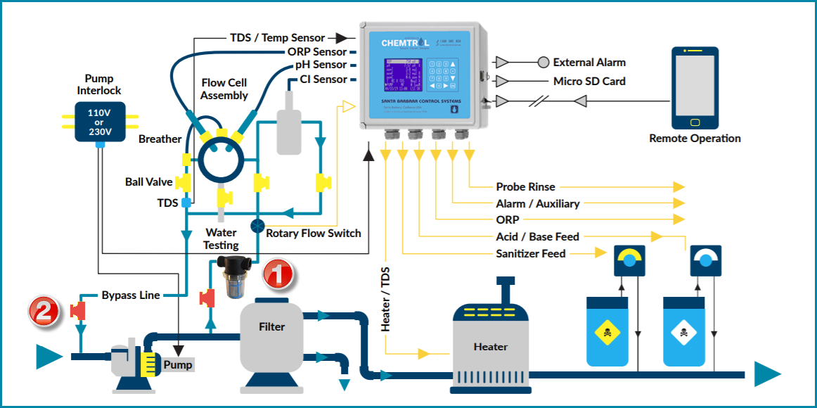
Bypass line & Feature diagram
Pool and Spa programmable controller (PC) range installation:
For optimal installation, it is recommended to mount the controller backboard on the right-hand side, with the plumbing manifold positioned on the left.
Alternatively, another viable option is to mount the plumbing manifold below the controller, maintaining an approximate 300mm gap between these two PVC backboards. This gap is essential for the servicing and maintenance of the chlorine (ppm) sensor.
Bypass line assembly (INLET)
Please connect to the discharge of the main recirculation filter pump, incorporating an inline strainer to ensure water cleanliness before sensor sampling. Ensure that the system maintains a maximum flow of 10 liters per minute (l/m) and a minimum flow of no less than 4 liters per minute (l/m).
*1 – Please ensure the installation includes an additional isolation valve positioned before the inline strainer. This valve is essential for facilitating maintenance and backwash processes, allowing for efficient servicing of the system.
Bypass line assembly (OUTLET)
Please ensure the connection is made before the pool main filter pump on the suction side. This arrangement is designed to promote consistent water flow out of the manifold.
*2 – It is crucial to incorporate an additional isolation valve into the system to facilitate maintenance and backwash processes. This valve will ensure efficient servicing of the system when needed.
Note: As each pool may have variations in filtration and recirculation equipment, we recommend consulting with a CHEMTROL® representative to determine the optimal connection for plumbing inlet/outlet on your facility.

Carbon Dioxide pH control
The schematic illustrates the installation principle, showcasing the recommended optional Automatic Switchover System for continuous pH control assurance.
Gas injection control is attained by connecting the 230v pH control output of the CHEMTROL® controller to the CO2 feeder cabinet.
Multiple CO2 gas cylinders can be manifolded together on each line to meet the required feed rate for maintaining proper pH levels.
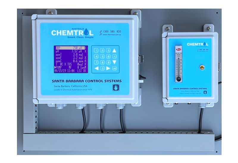
Controller with co2 feeder set
For a clean and organized installation, it is recommended to mount the controller and CO2 feeder side by side on a PVC backboard with a thickness of 10mm. Incorporate slotted cable management ducting for a tidy arrangement.
Assembly : grey PVC backboard 730×530 mm.

